I remember a client who brought in a pristine, late-model SUV. He’d spent five figures on a world-class sound system, but he had a “ghost in the machine.” Every time the bass hit, his GPS screen would flicker, and his HID headlights would dim so hard they almost cut out. He thought his new Car Battery was defective, but the problem was much deeper—and much cheaper to fix.
His factory wiring was the size of a piece of spaghetti. The manufacturer had designed the electrical system to handle 80 amps of load, but his amplifiers were demanding over 200 amps. His car was literally choking for air, electrically speaking. After we performed a proper Big 3 Upgrade, the “ghost” vanished. His voltage stabilized, his lights stopped dimming, and the bass suddenly had a “punch” it never had before.
If you are planning to run more than 1,000 watts RMS, you are likely hitting a bottleneck you don’t even see. This isn’t just an “upgrade”; it’s the foundation of your entire build. In this guide, I’m going to walk you through the “Why” and the “How” of the Big 3, ensuring your Car Audio Electrical System is ready for battle.
What Exactly is the “Big 3 Upgrade”?
The “Big 3” refers to the three primary cables that allow your charging system to function. Car manufacturers use the thinnest, cheapest wire possible to save weight and cost. While this is fine for a stock commuter car, it is a disaster for a high-performance Car Audio System.
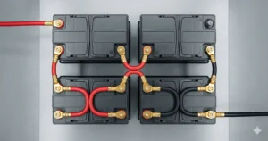
The upgrade involves adding (not necessarily replacing) heavy-duty 0 Gauge Wire to these three paths:
- Battery Negative to Chassis Ground: This is the most common bottleneck.
- Engine Block to Chassis Ground: Essential for the alternator’s return path.
- Alternator Positive to Battery Positive: The main charging line.
By reinforcing these paths, you decrease the total resistance of the circuit. Lower resistance means higher efficiency and less heat.
The Science of the Bottleneck: Why Factory Wire Fails
To understand why this matters, we have to look at how electricity returns to the source. Most people forget that the car’s metal frame (the chassis) is half of the circuit. If your ground wire from the battery to the frame is a puny 8-gauge wire, it doesn’t matter if you have 0-gauge going to your amp—the energy can’t get back to the battery fast enough.
When resistance is high, you experience Voltage Drop. This drop forces your equipment to pull more current to produce power, which generates heat. Heat kills amplifiers. The Big 3 is your primary defense against thermal failure.
Preparation: Your Checklist for Success
Don’t start this project until you have the right materials. Using “cheap” wire here defeats the purpose.
- 0 AWG OFC Cable: Do NOT use CCA (Copper Clad Aluminum). Only use OFC (Oxygen-Free Copper). It carries more current and won’t corrode like aluminum.
- Pure Copper Lugs: High-quality ring terminals are essential for a solid connection.
- Hydraulic Crimper: You cannot crimp 0-gauge with pliers. You need a solid, air-tight cold-weld crimp.
- Heat Shrink: To protect your connections from the harsh environment of the engine bay.
- External Fuse Holder: Mandatory for the alternator-to-battery run.
Step 1: Battery Negative to Chassis Ground
This is the easiest but most impactful step. Look at your battery’s negative terminal. Follow the wire that goes to the metal body of the car. Usually, it’s a thin, flimsy wire bolted to a painted surface.
- Find a solid ground point: Locate a thick part of the chassis or a factory grounding bolt.
- Scrape the paint: This is the most important part. Use a wire brush or sandpaper to get down to shiny, bare metal. Paint is an insulator!
- Install the cable: Secure your new 0 Gauge Wire from the battery terminal to the bare metal spot.
Step 2: Engine Block to Chassis Ground
Your High Output Alternator is bolted to your engine. For the current to return to the battery, it has to travel from the alternator case, through the engine block, through a ground strap, to the chassis.
Most factory engine ground straps are thin braided ribbons.
- Locate a large bolt on the engine block or the alternator bracket.
- Run your new cable from that bolt to your newly cleaned chassis ground point.
- Ensure the cable has enough “slack” to allow the engine to move on its mounts without snapping the wire.
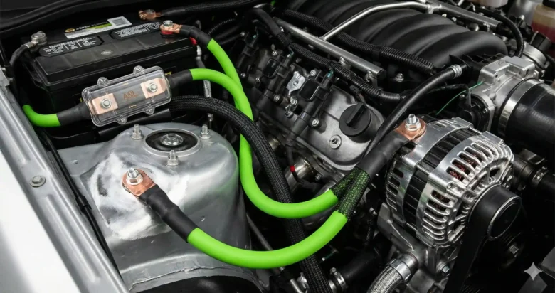
Step 3: Alternator Positive to Battery Positive
This is the “Power Run.” It allows the full amperage of your alternator to flow directly into the battery and the rest of the system without restriction.
CRITICAL SAFETY WARNING: This wire MUST be fused. If this wire rubs against the engine and shorts out without a fuse, your car will catch fire.
- Find the main output stud on the back of the alternator.
- Attach your fused 0-gauge cable.
- Run it to the positive terminal of your Car Battery.
- Mount the fuse holder (ANL style is best) as close to the battery as possible.
Common Mistakes to Avoid
In my 20 years of installing, I’ve seen the same errors over and over:
- Leaving the Paint: If you don’t scrape the paint, you are wasting your time. Metal-to-metal contact is the only way to ensure low resistance.
- Using CCA Wire: Aluminum wire in an engine bay is a recipe for disaster. It gets brittle and oxidizes. Always use OFC Battery Cable.
- Poor Crimping: Loose terminals create heat and can eventually arc, leading to electrical fires.
- No Fuses: Never run a power wire across an engine bay without a fuse. Period.
Testing Your Success: The Multimeter Check
Once you finish, you shouldn’t just “hear” the difference; you should measure it.
- Set your multimeter to DC Volts.
- Measure the voltage at the alternator.
- Measure the voltage at the battery terminals while the system is under load.
- If you did the Big 3 correctly, the difference between these two points should be nearly zero.
Conclusion: Don’t Starve Your Sound
The Big 3 Upgrade is the single best investment you can make in your vehicle’s audio journey. It’s not flashy, it doesn’t have a remote control, and you can’t see it from the driver’s seat. But without it, you are building your house on sand.
Mastering your Grounding and power delivery ensures that every dollar you spend on amplifiers and subwoofers actually translates into sound, not heat. Get your cables, grab your crimpers, and give your system the power it deserves.
FAQ: Non-Obvious Technical Questions
1. Should I remove the factory wiring when doing the Big 3? No. Leave the factory wiring in place. Electricity follows the path of least resistance. By adding the Big 3 cables, the current will naturally flow through the thicker wires, but having the factory wires as a secondary path doesn’t hurt and helps maintain factory computer sensors.
2. Is a 0-gauge wire overkill for a 1,000-watt system? There is no such thing as “too much” wire. While 4-gauge might suffice for 1,000 watts, 0-gauge allows for future upgrades and ensures the lowest possible resistance. It’s better to have it and not need it than to need it and not have it.
3. Does the Big 3 help with “Alternator Whine”? Yes, frequently. Alternator whine is often caused by a “ground loop” or poor grounding points. By consolidating your grounds and providing a massive, low-resistance path back to the battery, you often eliminate the electrical noise that causes that annoying high-pitched squeal in your speakers.